Reducing folium map sizes

Recently for a crimede-coder project I have been building out a custom library to make nice leaflet maps using the python folium library. See the example I have posted on my website. Below is a screenshot:

This map ended up having around 3000 elements in it, and was a total of 8mb. 8mb is not crazy to put on a website, but is at the stage where you can actually notice latency when first rendering the map.

Looking at the rendered html code though it was verbose in a few ways for every element. One is that lat/lon are in crazy precision by default, e.g. [-78.83229390597961, 35.94592660794455]. So a single polygon can have many of those. Six digits of precision for lat/lon is still under 1 meter of precision, which is plenty sufficient for my mapping applications. So you can reduce 8+ characters per lat/lon and not really make a difference to the map (you can technically have invalid polygons doing this, but this is really pedantic and should be fine).

A second part of the rendered folium html map for every object is given a full uuid, e.g. geo_json_a19eff2648beb3d74760dc0ddb58a73d.addTo(feature_group_2e2c6295a3a1c7d4c8d57d001c782482);. This again is not necessary. I end up reducing the 32 length uuids to the first 8 alphanumeric characters.

A final part is that the javascript is not minified – it has quite a bit of extra lines/spaces that are not needed. So here are my notes on using python code to take care of some of those pieces.

To clean up the precision for geometry objects, I do something like this.

import re

# geo is the geopandas dataframe
redg = geo.geometry.set_precision(10**-6).to_json()
# redg still has floats, below regex clips values
rs = r'(\d{2}\.|-\d{2}\.)(\d{6})(\d+)'
re.sub(rs,r'\1\2',redg)

As most of my functions add the geojson objects to the map one at a time (for custom actions/colors), this is sufficient to deal with that step (for markers, can round lat/lon directly). It may make more sense for the set precision to be 10**-5 and then clip the regex. (For these regex’s I am showing there is some risk they will replace something they should not, I think it will be pretty safe though.)

Then to clean up the UUID’s and extra whitespace, what I do is render the final HTML and then use regex’s:

# fol is the folium object
html = fol.get_root()
res = html.script.get_root().render()
# replace UUID with first 8
ru = r'([0-9a-f]{8})[0-9a-f]{4}[0-9a-f]{4}[0-9a-f]{4}[0-9a-f]{12}'
res = re.sub(ru,r'\1',res)
# clean up whitespace
rl = []
for s in res.split('\n'):
    ss = s.strip()
    if len(ss) > 0:
        rl.append(ss)
rlc = '\n'.join(rl)

There is probably a smarter way to do this directly with the folium object for the UUID’s. For whitespace though it would need to be after the HTML is written. You want to be careful with the cleaning up the whitespace step – it is possible you wanted blank lines in say a leaflet popup or tooltip. But for my purposes this is not really necessary.

Doing these two steps in the Durham map reduces the size of the rendered HTML from 8mb to 4mb. So reduced the size of the file by around 4 million characters! The savings will be even higher for maps with more elements.

One last part is my map has redundant svg inserted for the map markers. I may be able to use css to insert the svg, e.g. something like in css .mysvg {background-image: url("vector.svg");}, and then in the python code for the marker svg insert <div class="mysvg"></div>. For dense point maps this will also save quite a few characters. Or you could add in javascript to insert the svg as well (although that would be a bit sluggish I think relative to the css approach, although sluggish after first render if the markers are turned off).

I have not done this yet, as I need to tinker with getting the background svg to look how I want, but could save another 200-300 characters per marker icon. So will save a megabyte in the map for every 3000-5000 markers I am guessing.

The main reason I post webdemo’s on the crimede-coder site is that there a quite a few grifters in the tech space. Not just for data analysis, but for front-end development as well. I post stuff like that so you can go and actually see the work I do and its quality. There are quite a few people now claiming to be “data viz experts” who just embed mediocre Tableau or PowerBI apps. These apps in particular tend to produce very bad maps, so here you can see what I think a good map should look like.

If you want to check out all the interactions in the map, I posted a YouTube video walking through them

Durham hotspot map walkthrough of interactions

Hacking folium for nicer legends

I have accumulated various code to hack folium based maps over several recent projects, so figured would share. It is a bit too much to walk through the entire code inline in a blog post, but high level the extras this code does:

  • Adds in svg elements for legends in the layer control
  • Has a method for creating legends for choropleth maps
  • Inserts additional javascript to make a nice legend title (here a clickable company logo) + additional attributions

Here is the link to a live example, and below is a screenshot:

So as a quick rundown, if you are adding in an element to a folium layer, e.g.:

folium.FeatureGroup(name="Your Text Here",overlay=True,control=True)

You can insert arbitrary svg code into the name parameter, e.g. you can do something like <span><svg .... /svg>HotSpots</span>, and it will correctly render. So I have functions to make the svg icon match the passed color. So you can see I have a nice icon for city boundary’s, as well as a blobby thing for hotspots.

There in the end are so many possible parameters, I try to make reasonable functions without too crazy many parameters. So if someone wanted different icons, I might just make a different function (probably wouldn’t worry about passing in different potential svg).

I have a function for choropleth maps as well – I tend to not like the functions that you pass in a continuous variable and it does a color map for you. So here it is simple, you pass in a discrete variable with the label, and a second dictionary with the mapped colors. I tend to not use choropleth maps in interactive maps very often, as they are more difficult to visualize with the background map. But there you have it if you want it.

The final part is using javascript to insert the Crime Decoder logo (as a title in the legend/layer control), as well as the map attribution with additional text. These are inserted via additional javascript functions that I append to the html (so this wouldn’t work say inline in a jupyter notebook). The logo part is fairly simple, the map attribution though is more complicated, and requires creating an event listener in javascript on the correct elements.

The way that this works, I actually have to save the HTML file, then I reread the text back into python, add in additional CSS/javascript, and then resave the file.

If you want something like this for your business/website/analysts, just get in contact.

For next tasks, I want to build a demo-dashboard for Crime De-Coder (probably a serverless dashboard using wasm/pyscript). But in terms of leaflet extras, the ability to embed SVG into different elements, you can create charts in popups/tooltips, which would be a cool addition to my hotspots (click and it has a time series chart inside).

Use circles instead of choropleth for MSAs

We are homeschooling the kiddo at the moment (the plunge was reading by Bryan Caplan’s approach, and seeing with online schooling just how poor middle school education was). Wife is going through AP biology at the moment, and we looked up various job info on biomedical careers. Subsequently came across this gem of a map of MSA estimates from the Bureau of Labor Stats (BLS) Occupational Employment and Wage Stats series (OES).

I was actually mapping some metro stat areas (MSAs) at work the other day, and these are just terrifically bad geo areas to show via a choropleth map. All choropleth maps have the issue of varying size areas, but I never realized having somewhat regular borders (more straight lines) makes the state and county maps not so bad – these MSA areas though are tough to look at. (Wife says it scintillates for her if she looks too closely.)

There are various incredibly tiny MSAs next to giant ones that you will just never see in these maps (no matter what color scheme you use). Nevada confused for me quite a bit, until I zoomed in to see that there are 4 areas, Reno is just a tiny squib.

Another example is Boulder above Denver. (Look closely at the BLS map I linked, you can just make out Boulder if you squint, but I cannot tell what color it corresponds to in the legend.) The outline heavy OES maps, which are mostly missing data, are just hopeless to display like this effectively. Reno could be the hottest market for whatever job, and it will always be lost in this map if you show employment via the choropleth approach. So of course I spent the weekend hacking together some maps in python and folium.

The BLS has a public API, but I was not able to find the OES stats in that. But if you go through the motions of querying the data and muck around in the source code for those queries, you can see they have an undocumented API call to generate json to fill the tables. Then using this tool to convert the json calls to python (thank you Hacker News), I was able to get those tables into python.

I have these functions saved on github, so check out that source for the nitty gritty. But just here quickly, here is a replicated choropleth map, showing the total employees for bio jobs (you can go to here to look up the codes, or run my function bls_maps.ocodes() to get a pandas dataframe of those fields).

# Creating example bls maps
from bls_geo import *

# can check out https://www.bls.gov/oes/current/oes_stru.htm
bio = '172031'
bio_stats = oes_geo(bio)
areas = get_areas() # this takes a few minutes
state = state_albers()
geo_bio = merge_occgeo(bio_stats,areas)

ax = geo_bio.plot(column='Employment',cmap='inferno',legend=True,zorder=2)
state.boundary.plot(ax=ax,color='grey',linewidth=0.5,zorder=1)
ax.set_ylim(0.1*1e6,3.3*1e6)
ax.set_xlim(-0.3*1e7,0.3*1e7)   # lower 48 focus (for Albers proj)
ax.set_axis_off()
plt.show()

And that is not much better than BLSs version. For this data, if you are just interested in looking up or seeing the top metro areas, just doing a table, e.g. above geo_bio.to_excel('biojobs.xlsx'), works just as well as a map.

So I was surprised to see Minneapolis pop up at the top of that list (and also surprised Raleigh doesn’t make the list at all, but Durham has a few jobs). But if you insist on seeing spatial trends, I prefer to go the approach of mapping proportion or graduate circles, placing the points at the centroid of the MSA:

att = ['areaName','Employment','Location Quotient','Employment per 1,000 jobs','Annual mean wage']
form = ['',',.0f','.2f','.2f',',.0f']

map_bio = fol_map(geo_bio,'Employment',['lat', 'lon'],att,form)
#map_bio.save('biomap.html')
map_bio #if in jupyter can render like this

I am too lazy to make a legend, you can check out nbviewer to see an interactive Folium map, which I have tool tips (similar to the hover for the BLS maps).

Forgive my CSS/HTML skills, not sure how to make nicer popups. So you lose the exact areas these MSA cover in this approach, but I really only expect a general sense from these maps anyway.

These functions are general enough for whatever wage series you want (although these functions will likely break when the 2021 data comes out). So here is the OES table for data science jobs:

I feel going for the 90th percentile (mapping that to the 10 times programmer) is a bit too over the top. But I can see myself reasonably justifying 75th percentile. (Unfortunately these agg tables don’t have a way to adjust for years of experience, if you know of a BLS micro product I could do that with let me know!). So you can see here the somewhat inflated salaries for the SanFran Bay area, but not as inflated as many might have you think (and to be clear, these are for 2020 survey estimates).

If we look at map of data science jobs, varying the circles by that 75th annual wage percentile, it looks quite uniform. What happens is we have some real low outliers (wages under 70k), resulting in tiny circles (such as Athen’s GA). Most of the other metro regions though are well over 100k.

In more somber news, those interactive maps are built using Leaflet as the backend, which was create by a Ukranian citizen, Vladimir Agafonkin. We can do amazing things with open source code, but we should always remember it is on the backs of someones labor we are able to do those things.

Creating high crime sub-tours

I was nerdsniped a bit by this paper, Targeting Knife-Enabled Homicides For Preventive Policing: A Stratified Resource Allocation Model by Vincent Hariman and Larry Sherman (HS from here on).

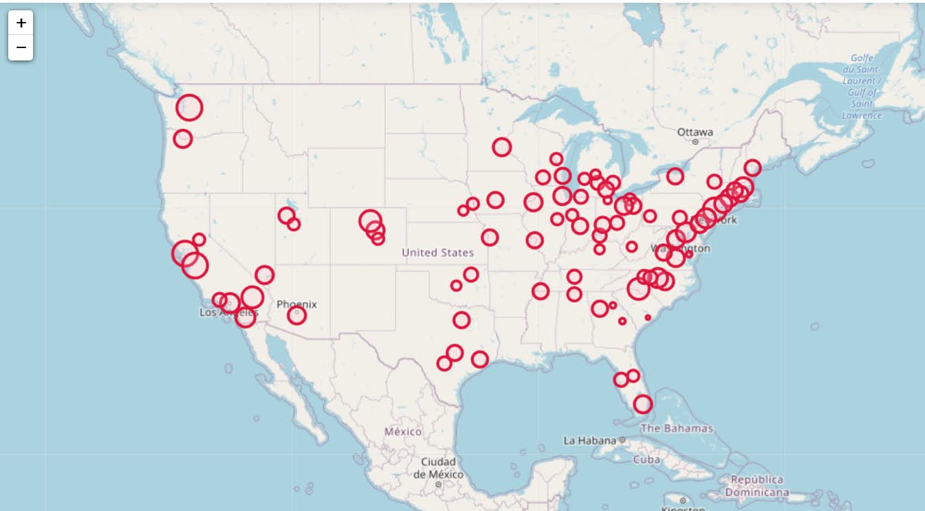
It in, HS attempt to define a touring schedule based on knife crime risk at the lower super output area in London. So here are the identified high risk areas:

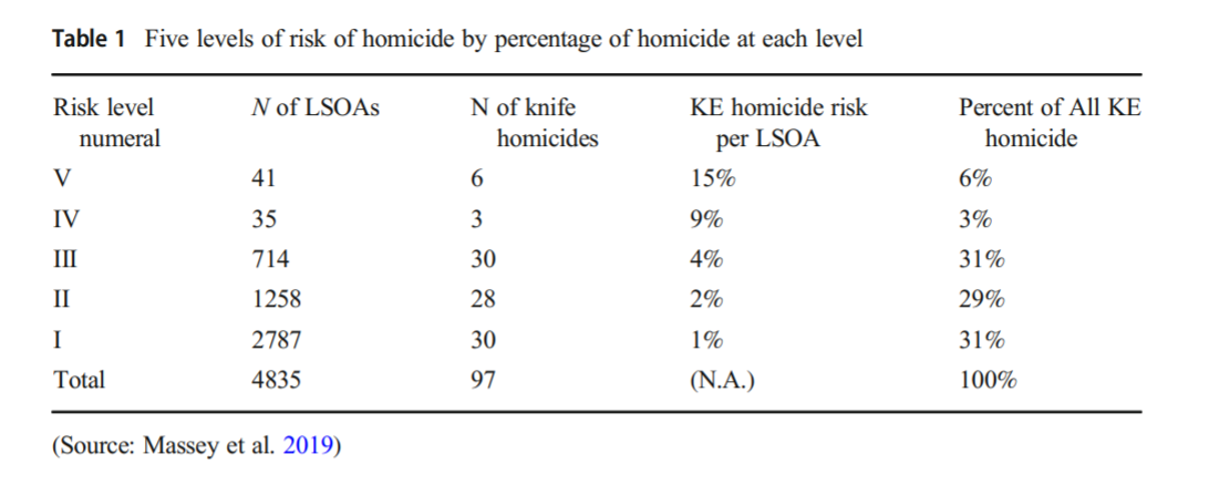
And here are HS’s suggested hot spot tours schedule.

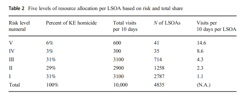
This is ad-hoc, but an admirable attempt to figure out a reasonable schedule. As you can see in their tables, the ‘high’ knife crime risk areas still only have a handful of homicides, so if reducing homicides is the objective, this program is a bit dead in the water (I’ve written about the lack of predictive ability of the model here).

I don’t think defining tours to visit everywhere makes sense, but I do think a somewhat smaller in scope question, how to figure out geographically informed tours for hot spot areas does. So instead of the single grid cell target ala PredPol, pick out multiple areas to visit for hot spots. (I don’t imagine the 41 LSOA areas are geographically contiguous either, e.g. it would make more sense to pick a tour for areas connected than for areas very far apart.)

Officers don’t tend to like single tiny areas either really, and I think it makes more sense to widen the scope a bit. So here is my attempt to figure those reasonable tours out.

Defining the Problem

The way I think about that problem is like this, look at the hypothetical diagram below. We have two choices for the hot spot location we are targeting, where the crime counts for locations are noted in the text label.

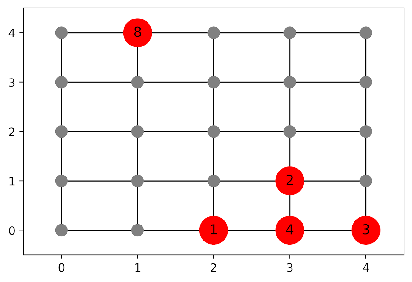
In the select the top hot spot (e.g. PredPol) approach, you would select the singlet grid cell in the top left, it is the highest intensity. We have another choice though, the more spread out hot spot in the lower right. Even though it is a lower density, it ends up capturing more crime overall.

I subsequently formulated an integer linear program to try to tackle the problem of finding good sub-tours through the graph that cumulatively capture more crime. So with the above graph, if I select two subtours, I get the results as (where nodes are identified by their (x,y) position):

  • ['Begin', (1, 4), 'End']
  • ['Begin', (4, 0), (4, 1), (3, 1), (3, 0), (2, 0), 'End']

So it can select singlet areas if they are islands (the (1,4) area in the top left), but will grow to wind through areas. Also note that the way I have programmed this network, it doesn’t skip the zero area (4,1) (it needs to go through at least one in the bottom right unless it doubles back on itself).

I will explain the meaning of the begin and end nodes below in my description of the linear program. It ends up being sort of a mash-up of traveling salesman type vehicle routing and min cost max flow type problems.

The Linear Program

The way I think about this problem formulation is like this: we have a directed graph, in which you can say, OK I start from location A, then can go to B, than go to C. In my set of decision variables, I have choices that look like this, where the first subscript denotes the from node, and the second subscript denotes the to node.

D_ab := node a -> node b
D_bc := node b -> node c

etc. In our subsequent linear program, the destination node is the node that we calculate our cumulative crime density statistics. So if node B had 10 crimes and 0.1 square kilometers, we would have a density of 100 crimes per square kilometer.

Now to make this formulation work, we need to add in a set of special nodes into our usual location network. These nodes I call ‘Begin’ and ‘End’ nodes (you may also call them source/sink nodes though). The begin nodes all look like this:

D_{begin},a
D_{begin},b
D_{begin},c

So you do that for every node in your network. Then you have End nodes as well, e.g.

D_a,{end}
D_b,{end}
D_c,{end}

In this formulation, since we are only concerned about the crime stats for the to node, not the from node, the Begin nodes just inherit the crime density stats from the original node data. For the end nodes though, you just set their objective value stats to zero (they are only relevant to define the constraints).

Now here is my linear program formulation:

Maximize 
  Sum [ D_ij ( CrimeDensity_j - DensityPenalty_j ) ]

Subject To:

 1. Sum( D_in for each neighbor of n ) <= 1, 
      for each original node n
 2. Sum( D_in for each neighbor of n ) =  Sum( D_ni for each neighbor of n ), 
      for each original node n
 3. Sum( D_bi for each begin node ) = k routes
 4. Sum( D_ie for each end node ) = k routes
 5. Sum( D_ij + D_ji ) <= 1, for each unique i,j pair
 6. D_ij is an element of {0,1}

Constraint 1 is a flow constraint. If a node has an incoming edge set to one, it cannot have any other incoming edge set to one (so a location can only be chosen once).

Constraint 2 is a constraint that says if an incoming node is selected, one of the outgoing edges needs to be selected.

Constraints 3 & 4 determine the number of k tours/routes to choose in the end. Since the begin/end nodes are special we have k routes going out of the begin nodes, and k routes going into the end nodes.

With just these constraints, you can still get micro-cycles I found. So something like, X -> Z -> X. Constraint 5 (for only the undirected edges) prevents this from happening.

Constraint 6 is just setting the decision variables to binary 0/1. So it is a mixed integer linear program.

The final thing to note is the objective function, I have CrimeDensity_j - DensityPenalty_j, so what exactly is DensityPenalty? This is a value that penalizes visiting areas that are below this threshold. Basically the way that this works is that, the density penalty sets an approximate threshold for the minimum density a tour should contain.

I suggest a default of a predictive accuracy index of 10. Where do I get 10 you ask? Weisburd’s law of crime concentration suggests 5% of the areas should contain 50% of the crime, which is a PAI of 0.5/0.05 = 10. In my example with DC data then I just calculate the actual density of crime per unit area that corresponds to a PAI of 10.

You can adjust this though, if you prefer smaller tours of higher crime density you would up the value. If you prefer longer tours decrease it.

This is the best way I could figure out how to trade off the idea of spreading out the targeted hot spot vs selecting the best areas. If you spread out you will ultimately have a lower density. This turns it into a soft objective penalty to try to keep the selected tours at a particular density threshold (and will scoop up better tours if they are available). For awhile I tried to figure out if I could maximize the PAI metric, but it is the case with larger areas the PAI will always go down, so you need to define the objective some other way.

This formulation I only consider linked nodes (unlike the usual traveling salesman in which it is a completely linked distance graph). That makes it much more manageable. In this formulation, if you have N as the number of nodes/areas, and E is the number of directed edges between those areas, we will then have:

  • 2*N + E decision variables
  • 2 + 2*N + E/2 constraints

Generally if you are doing directly connected areas in geographic networks (i.e. contiguity connections), you will have less than 8 (typically more like an average of 6) neighbors per each area. So in the case of the 4k London lower super output areas, if I chose tours I would guess it would end up being fewer than 2*4,000 + 8*4,000 = 40,000 decision variables, and then fewer than that constraints.

Since that is puny (and I would suggest doing this at a smaller geographic resolution) I tested it out on a harder network. I used the data from my dissertation, a network of 21,506 street units (both street segments and intersections) in Washington, D.C. The contiguity I use for these micro units is based on the Voronoi tessellation, so tends to have more neighbors than you would with a strictly road based network connectivity. Still in the end it ends up being a shade fewer than 200k decision variables and 110k constraints. So is a better test for in the wild whether the problem can be feasibly solved I think.

Example with DC Data

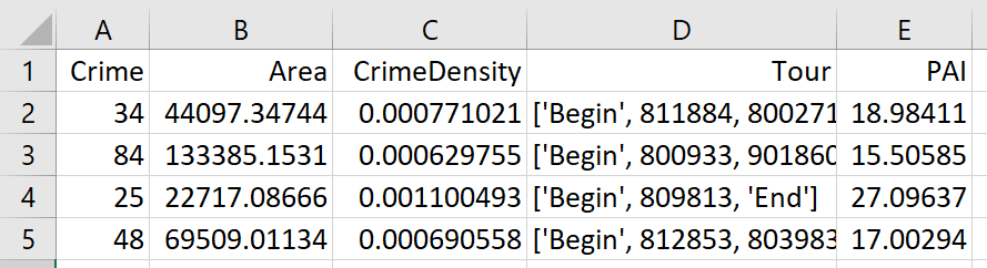
Here I have posted the python code and data used for this analysis, I end up having a nice function that you just submit your network with the appropriate attributes and out pops the different tours.

So I end up doing examples of 4 and 8 subtours based on 2011 violent UCR crime data (agg assaults, robberies, and homicides, no rapes in the public data). I use for the penalty that PAI = 10 threshold, so it should limit tours to approximately that value. It only ends up taking 2 minutes for the model to converge for the 4 tours and less than 2.5 minutes for the 8 tours on my desktop. So it should be not a big problem to up the decision variables to more sub-areas and still be solvable in real life applications.

The area estimates are in square meters, hence the high numbers. But on the right you can see that each sub-tour has a PAI above 10.

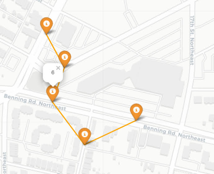
Here is an interactive map for you to zoom into each 4 subtour example. Below is a screenshot of one of the subtours. You can see that since I have defined my connected areas in terms of Voronoi tessalations, they don’t exactly follow the street network.

For the 8 tour example, it ends up returning several zero tours, so it is not possible in this data to generate 8 sub-tours that meet that PAI >= 10 threshold.

You can see that it ends up being the tours have higher PAI values, but lower overall crime counts.

You may think, why does it not pick at least singlet areas with at least one crime? It ends up being that I weight areas here by their area (this formulation would be better with grid cells of equal area, so my objective function is technically Sum [ D_ij * w_j *( CrimeDensity_j - DensityPenalty_j ) ], where w_j is the percent of the total area (so the denominator in the PAI calculation). So it ends up picking areas that are the tiniest areas, as they result in the smallest penalty to the objective function (w_j is tiny). I think this is OK though in the end – I rather know that some of the tours are worthless.

You can also see I get one subtour that is just under the PAI 10 threshold. Again possible here, but should be only slightly below in the worst case scenario. The way the objective function works is that it is pretty tricky to pick out subtours below that PAI value but still have a positive contribution to the overall objective function.

Future Directions

The main thing I wish I could do with the current algorithm (but can’t the way the linear program is set up), is to have minimum and maximum tour area/length constraints. I think I can maybe do this by adapting this code (I’m not sure how to do the penalties/objectives though). So if others have ideas let me know!

I admit that this may be overkill, and maybe just doing more typical crime clustering algorithms may be sufficient. E.g. doing DBSCAN hot spots like I did here.

But this is my best attempt shake at the problem for now!