Running files locally in SPSS

Say I made alittle python script for a friend to scrape data from a website whenever they wanted updates. I write my python script, say scrape.py, and a run_scrape.bat file for my friend on their windows machine (or run_scrape.sh on Mac/Unix). And inside the bat file has the command:

python scrape.py

I tell my friend save those two files in whatever folder you want, you just need to double click the bat file and it will save the scraped data into the same folder. Here the bat file is run locally, it sets the current directory to wherever the bat file is located.

This is how the majority of code is packaged – can clone from github or email a zip file, and it will just work no matter where the local user saves those scripts. I need to have my friend have their python environment set up correctly, but most of the stuff I do I can say download Anaconda and click yes to setting python on the path and they are golden.

SPSS makes things more painful, say I added SPSS to my environment variable in my windows machine, and I run from the command prompt an SPSS production job:

cd "C:\Users\Andrew"
spss print_dir.spj" -production silent

And say the spj file, all it does is call a syntax show.sps which has as the only command SHOW DIR. This still prints out wherever SPSS is installed as the current working directory inside of the SPSS session. On my machine currently C:\Program Files\IBM\SPSS Statistics. So SPSS takes over the location of the current directory. Also we can open up the spj file (it is just a plain text xml file). Here is what a current spj file looks like for me (note it is all on one line as well!):

And that file also has several hard coded file locations. So to get the same behavior as python scrape.py earlier, we need to do dynamically set the paths in the production job as well, not just alter the command line scripts. This can be done with a little command line magic in windows, dynamically replacing the right text in the spj file. So in a bat file, you can do something like:

@echo on
set "base=%cd%"
:: code to define SPJ (SPSS production file)
echo ^<?xml version=^"1.0^" encoding=^"UTF-8^" standalone=^"no^"?^>^<job xmlns=^"http://www.ibm.com/software/analytics/spss/xml/production^" codepageSyntaxFiles=^"false^" print=^"false^" syntaxErrorHandling=^"continue^" syntaxFormat=^"interactive^" unicode=^"true^" xmlns:xsi=^"http://www.w3.org/2001/XMLSchema-instance^" xsi:schemaLocation=^"http://www.ibm.com/software/analytics/spss/xml/production http://www.ibm.com/software/analytics/spss/xml/production/production-1.4.xsd^"^>^<locale charset=^"UTF-8^" country=^"US^" language=^"en^"/^>^<output imageFormat=^"jpg^" imageSize=^"100^" outputFormat=^"text-codepage^" outputPath=^"%base%\job_output.txt^" tableColumnAutofit=^"true^" tableColumnBorder=^"^|^" tableColumnSeparator=^"space^" tableRowBorder=^"-^"/^>^<syntax syntaxPath=^"%base%\show.sps^"/^>^<symbol name=^"setdir^" quote=^"true^"/^>^</job^> > transfer_job.spj
"C:\Program Files\IBM\SPSS Statistics\stats.exe" "%base%\transfer_job.spj" -production silent -symbol @setdir "%base%"

It would be easier to use sed to find/replace the text for the spj file instead of the superlong one-liner on echo, but I don’t know if Window’s always has sed installed. Also note the escape characters (it is crazy how windows parses this single long line, apparently the max length is around 32k characters though).

You can see in the call to the production job, I pass a parameter, @setdir, and expand it out in the shell using %base%. In show.sps, I now have this line:

CD @setdir.

And now SPSS has set the current directory to wherever you have the .bat file and .sps syntax file saved. So now everything is dynamic, and runs wherever you have all the files saved. The only thing that is not dynamic in this setup is the location of the SPSS executable, stats.exe. So if you are sharing SPSS code like this, you will need to either tell your friend to add C:\Program Files\IBM\SPSS Statistics to their environment path, or edit the .bat file to the correct path, but otherwise this is dynamically run in the local folder with all the materials.

Using precision to plan experiments (SPSS)

SPSS Version 28 has some new nice power analysis facilities. Here is some example code to test the difference in proportions, with sample sizes equal between the two groups, and the groups have an underlying proportion of 0.1 and 0.2.

POWER PROPORTIONS INDEPENDENT
  /PARAMETERS TEST=NONDIRECTIONAL SIGNIFICANCE=0.05 POWER=0.6 0.7 0.8 0.9 NRATIO=1 
    PROPORTIONS=0.1 0.2 METHOD=CHISQ ESTIMATE=NORMAL CONTINUITY=TRUE POOLED=TRUE
  /PLOT TOTAL_N.

So this tells you the sample size to get a statistically significant difference (at the 0.05 level) between two groups for a proportion difference test (here just a chi square test). And you can specify the solution for different power estimates (here a grid of 0.6 to 0.9 by 0.1), as well as get a nice plot.

So this is nice for academics planning factorial experiments, but I often don’t personally plan experiments this way. I typically get sample size estimates via thinking about precision of my estimates. In particular I think to myself, I want subgroup X to have a confidence interval width of no more than 5%. Even if you want to extend this to testing the differences between groups this is OK (but will be conservative), because even if two confidence intervals overlap the two groups can still be statistically different (see this Geoff Cumming reference).

So for example a friend the other day was asking about how to sample cases for an audit, and they wanted to do subgroup analysis in errors between different racial categories. But it was paper records, so they needed to just get an estimate of the total records to sample upfront (can’t really control the subgroup sizes). I suggested to estimate the precision they wanted in the smallest subgroup of interest for the errors, and base the total sample size of the paper audit on that. This is much easier to plan than worrying about a true power analysis, in which you also need to specify the expected differences in the groups.

So here is a macro I made in SPSS to generate precision estimates for binomial proportions (Clopper Pearson exact intervals). See my prior blog post for different ways to generate these intervals.

* Single proportion, precision.
DEFINE !PrecisionProp (Prop = !TOKENS(1)
                      /MinN = !TOKENS(1)
                      /MaxN = !TOKENS(1)
                      /Steps = !DEFAULT(100) !TOKENS(1) 
                      /DName = !DEFAULT("Prec") !TOKENS(1) )
INPUT PROGRAM.
COMPUTE #Lmi = LN(!MinN).
COMPUTE #Step = (LN(!MaxN) - #Lmi)/!Steps.
LOOP #i = 1 TO (!Steps + 1).
  COMPUTE N = EXP(#Lmi + (#i-1)*#Step).
  COMPUTE #Suc = N*!Prop.
  COMPUTE Prop = !Prop.
  COMPUTE Low90 = IDF.BETA(0.05,#Suc,N-#Suc+1).
  COMPUTE High90 = IDF.BETA(0.95,#Suc+1,N-#Suc).
  COMPUTE Low95 = IDF.BETA(0.025,#Suc,N-#Suc+1).
  COMPUTE High95 = IDF.BETA(0.975,#Suc+1,N-#Suc).
  COMPUTE Low99 = IDF.BETA(0.005,#Suc,N-#Suc+1).
  COMPUTE High99 = IDF.BETA(0.995,#Suc+1,N-#Suc).
  END CASE.
END LOOP.
END FILE.
END INPUT PROGRAM.
DATASET NAME !DName.
FORMATS N (F10.0) Prop (F3.2).
EXECUTE.
!ENDDEFINE.

This generates a new dataset, with a baseline proportion of 50%, and shows how the exact confidence intervals change with increasing the sample size. Here is an example generating confidence intervals (90%,95%, and 99%) for sample sizes from 50 to 3000 with a baseline proportion of 50%.

!PrecisionProp Prop=0.5 MinN=50 MaxN=3000.

And we can go and look at the generated dataset. For sample size of 50 cases, the 90% CI is 38%-62%, the 95% CI is 36%-64%, and the 99% CI is 32%-68%.

For sample sizes of closer to 3000, you can then see how these confidence intervals decrease in width to changes in 4 to 5%.

But I really just generated the data this way to do a nice error bar chart to visualize:

*Precision chart.
GGRAPH
  /GRAPHDATASET NAME="graphdataset" VARIABLES=Prop N Low90 High90 Low95 High95 Low99 High99
  /GRAPHSPEC SOURCE=INLINE.
BEGIN GPL
  SOURCE: s=userSource(id("graphdataset"))
  DATA: N=col(source(s), name("N"))
  DATA: Prop=col(source(s), name("Prop"))
  DATA: Low90=col(source(s), name("Low90"))
  DATA: High90=col(source(s), name("High90"))
  DATA: Low95=col(source(s), name("Low95"))
  DATA: High95=col(source(s), name("High95"))
  DATA: Low99=col(source(s), name("Low99"))
  DATA: High99=col(source(s), name("High99"))
  DATA: N=col(source(s), name("N"))
  GUIDE: text.title(label("Base Rate 50%"))
  GUIDE: axis(dim(1), label("Sample Size"))
  GUIDE: axis(dim(2), delta(0.05))
  SCALE: linear(dim(1), min(50), max(3000))
  ELEMENT: area.difference(position(region.spread.range(N*(Low99+High99))), color.interior(color.grey), 
           transparency.interior(transparency."0.6"))
  ELEMENT: area.difference(position(region.spread.range(N*(Low95+High95))), color.interior(color.grey), 
           transparency.interior(transparency."0.6"))
  ELEMENT: area.difference(position(region.spread.range(N*(Low90+High90))), color.interior(color.grey), 
           transparency.interior(transparency."0.6"))
  ELEMENT: line(position(N*Prop))
END GPL.

So here the lightest gray area is the 99% CI, the second lightest is the 95%, and the darkest area is the 90% CI. So here you can make value trade offs, is it worth it to get an extra precision of under 10% by going from 500 samples to 1000 samples? Going from 1500 to 3000 you don’t gain as much precision as going from 500 to 1000 (diminishing returns).

It is easier to see the progression of the CI’s when plotting the sample size on a log scale (or sometimes square root), although often times costs of sampling are on the linear scale.

You can then change the macro arguments if you know your baseline is likely to not be 50%, but say here 15%:

!PrecisionProp Prop=0.15 MinN=50 MaxN=3000.

So you can see in this graph that the confidence intervals are smaller in width than the 50% – a baseline of 50% results in the largest variance estimates for binary 0/1 data, so anything close to 0% or 100% will result in smaller confidence intervals. So this means if you know you want a precision of 5%, but only have a rough guess as to the overall proportion, planning for 50% baseline is the worst case scenario.

Also note that when going away from 50%, the confidence intervals are asymmetric. The interval above 15% is larger than the interval below.

A few times at work I have had pilots that look something like “historical hit rates for these audits are 10%, I want the new machine learning model to increase that to 15%”.

So here I can say, if we can only easily use a sample of 500 cases for the new machine learning model, the precision I expect to be around 11% to 19%. So cutting a bit close to be sure it is actually above the historical baseline rate of 10%. To get a more comfortable margin we need sample sizes of 1000+ in this scenario.

Difference in independent effects for multivariate analysis (SPSS)

For some reason my various posts on testing differences in coefficients are fairly high in google search results. Arden Roeder writes in with another related question on this:

Good evening Dr. Wheeler,

I am a PhD candidate at the University of Oklahoma working on the final phases of data analysis for my dissertation. I found an article on your website that almost answers a question I have about a potential statistical test, and I’m hoping you might be able to help me fill in the gaps.

If you are willing to help me out, I would greatly appreciate it, and if not, I completely understand!

Here’s the setup: I have two independent variables (one measured on a 6-point Likert scale, the other on a 7-point) and six dependent variables. I have hypothesized that IV1 would be a stronger predictor of three of the DVs, and that IV2 would be a stronger predictor of the other three DVs. I ran multiple linear regression tests for each of the DVs, so I have the outputs for those. I know I can compare the standardized betas just to see strength, but what I’d like to know is how I can determine whether the difference between the beta weights is significant, and then to assess this for each of the six DVs.

From reading through your post, it seems like the fourth scenario you set up is quite close to what I’m trying to do, but I’m not sure how to translate the covariance output I have (I’m using SPSS) to what you’ve displayed here. Can I simply square the standard errors I have to get the numbers on the diagonal, and then grab the covariance from the SPSS output and solve accordingly? (I also reviewed your writing here about using the GLM procedure as well, but can’t seem to align my outputs with your examples there either.)

Here’s a sample of the numbers I’m working with:

Any insights you can offer on 1) whether this is the right test to give me the answers I’m looking for about whether the betas are significantly different and 2) how to set up and interpret the results correctly would be a tremendous help.

For 1, yes I think this is an appropriate way to set up the problem. For 2, if sticking to SPSS it is fairly simple syntax in GLM:

*****************************.
*Contrasts with X1 - X2 effect across the variables.
GLM Y1 Y2 Y3 Y4 Y5 Y6 WITH X1 X2
  /DESIGN=X1 X2
  /PRINT PARAMETER
  /LMATRIX = "T1"
             X1  1
             X2 -1.
*****************************.

To get this to do the standardized coefficients, Z-score your variables before the GLM command (this is assuming you are estimating a linear model, and not a non-linear model like logit/Poisson). (I have full simulation SPSS code at the end of the post illustrating.)

Note that when I say the covariance between beta coefficients, this is NOT the same thing as the covariance between the original metrics. So the correlation matrix for X1 vs X2 here does not give us the information we need.

For 2, the reporting part, you can see the Contrast results K matrix table in SPSS. I would just transpose that table, make a footnote/title this is testing X1 – X2, and then just keep the columns you want. So here is the original SPSS contrast table for this result:

And here is how I would clean up the table and report the tests:

SPSS Simulation Code

Here I just simulate independent X’s, and give the Y’s consistent effects. You could also simulate multivariate data with specified correlations if you wanted to though.

****************************************************.
* Simulated data to illustrate coefficient diff.
* tests.
SET SEED 10.
INPUT PROGRAM.
LOOP #i = 1 TO 10000.
COMPUTE Id = #i.
END CASE.
END LOOP.
END FILE.
END INPUT PROGRAM.

COMPUTE X1 = RV.NORMAL(0,1).
COMPUTE X2 = RV.NORMAL(0,1).
COMPUTE Y1 = 1.5*X1 + 0.5*X2 + RV.NORMAL(0,1).
COMPUTE Y2 = 1.5*X1 + 0.5*X2 + RV.NORMAL(0,1).
COMPUTE Y3 = 1.5*X1 + 0.5*X2 + RV.NORMAL(0,1).
COMPUTE Y4 = 0.5*X1 + 1.5*X2 + RV.NORMAL(0,1).
COMPUTE Y5 = 0.5*X1 + 1.5*X2 + RV.NORMAL(0,1).
COMPUTE Y6 = 0.5*X1 + 1.5*X2 + RV.NORMAL(0,1).
EXECUTE.

*Contrasts with X1 - X2 effect across the variables.
GLM Y1 Y2 Y3 Y4 Y5 Y6 WITH X1 X2
  /DESIGN=X1 X2
  /PRINT PARAMETER
  /LMATRIX = "Contrast X1 - X2"
             X1  1
             X2 -1.

*And here is an example stacking equations and using EMMEANS. 
*Stacking equation approach, can work for various.
*Generalized linear models, etc.
VARSTOCASES
  /MAKE Y FROM Y1 TO Y6
  /Index Outcome.

GENLIN Y BY Outcome WITH X1 X2
  /MODEL Outcome X1 X2 Outcome*X1 Outcome*X2
    DISTRIBUTION=NORMAL LINK=IDENTITY
 /CRITERIA COVB=ROBUST
 /REPEATED SUBJECT=Id CORRTYPE=UNSTRUCTURED
 /EMMEANS TABLES=Outcome CONTROL= X1(1) X2(-1).
****************************************************.

Python f string number formatting and SPSS break long labels

Another quick blog post, as moving is not 100% crazy all the time now, but I need a vacation after all that work. So two things in this blog post: formatting numeric f strings in python, and breaking long labels in SPSS meta-data.

Python f-string numeric formatting

This is super simple, but I can never remember it (so making a quick blog post for my own reference). As of python 3.6, you can use f-strings to do simple text substitution. So if you do:

x = 2/3
sub_str = f'This proportion is {x}'
print(sub_str)

Then we will get printed out This proportion is 0.6666666666666666. So packing global items inside of {} expands within the f string. While for more serious string subsitution (like creating parameterized SQL queries), I like to use string templates, these f-strings are very nice to print short messages to the console or make annotations in graphs.

Part of this note is that I never remember how to format these strings. If you are working with integers it is not a big deal, but as you can see above I often do not want to print out all those decimals inside my particular message. A simple way to format the strings are:

f'This proportion is {x:.2f}'

And this prints out to two decimal places 'This proportion is 0.67'. If you have very big numbers (say revenue), you can do something like:

f'This value is ${x*10000:,.0f}'

Which prints out 'This value is $6,667' (so you can modify objects in place, to say change a proportion to a percentage).

Note also to folks that you can have multi-line f-strings by using triple quotes, e.g.:

f'''This is a super
long f-string for {x:.2f}
on multiple lines!'''

But one annoying this is that you need to keep the whitespace correct inside of functions even inside the triple string. So those are cases I like using string templates. But another option is to break up the string and use line breaks via \n.

long_str = (f'This is line 1\n'
            f'Proportion is {x:.1f}\n'
            f'This is line 3')
print(long_str)

Which prints out:

This is line 1
Proportion is 0.7
This is line 3

You could do the line breaks however, either at the beginning of each line or at the end of each line.

SPSS break long labels

This was in reference to a project where I was working with survey data, and for various graphs I needed to break up long labels. So here is an example to illustrate the problem.

* Creating simple data to illustrate.
DATA LIST FREE / X Y(2F1.0).
BEGIN DATA
1 1
2 2
3 3
4 4
END DATA.
DATASET NAME LongLab.
VALUE LABELS X
  1 'This is a reallllllllly long label'
  2 'short label'
  3 'Super long unnecessary label that is long'
  4 'Again another long label what is up with this'
.
VARIABLE LABELS
  X 'Short variable label'
  Y 'This is also a super long variable label that is excessive!'
.
EXECUTE.

GGRAPH
  /GRAPHDATASET NAME="g" VARIABLES=X Y
  /GRAPHSPEC SOURCE=INLINE.
BEGIN GPL
  SOURCE: s=userSource(id("g"))
  DATA: X=col(source(s), name("X"), unit.category())
  DATA: Y=col(source(s), name("Y"))
  COORD: rect(dim(1,2), transpose())
  GUIDE: axis(dim(1))
  GUIDE: axis(dim(2), label("Value"))
  SCALE: linear(dim(2), include(0))
  ELEMENT: interval(position(X*Y))
END GPL.

So you can see, SPSS shrinks the data to accommodate the long labels. (I don’t know how to control the behavior in the graph or the chart template itself, so not sure why only this gets wrapped for the first label.) So we can use the \n line break trick again in SPSS to get these to split where we prefer. Here are some python functions to do the splitting (which I am sure can be improved upon), as well as to apply the splits to the current SPSS dataset. You can decide the split where you want the line to be broken, and so if a word goes above that split level it wraps to the next line.

* Now some python to wrap long labels.
BEGIN PROGRAM PYTHON3.
import spss, spssaux

# Splits a long string with line breaks
def long_str(x,split):
    split_str = x.split(" ")
    cum = len(split_str[0])
    cum_str = split_str[0]
    for s in split_str[1:]:
        cum += len(s) + 1
        if cum <= split:
            cum_str += " " + s
        else:
            cum_str += r"\n" + s
            cum = len(s)
    return cum_str

# This grabs all of the variables in the current SPSS dataset
varList = [spss.GetVariableName(i) for i in range(spss.GetVariableCount())]

# This looks at the VALUE LABELS and splits them up on multiple lines
def split_vallab(vList, lsplit):
    vardict = spssaux.VariableDict()
    for v in vardict:
        if v in vList:
            vls= v.ValueLabels.keys()
            if vls:
                for k in vls:
                    ss = long_str(v.ValueLabels[k], lsplit)
                    if ss != v.ValueLabels[k]:
                        vn = v.VariableName
                        cmd = '''ADD VALUE LABELS %(vn)s %(k)s \'%(ss)s\'.''' % ( locals() )
                        spss.Submit(cmd)

# I run this to split up the value labels
split_vallab(varList, 20)

# This function is for VARIABLE LABELS
def split_varlab(vList,lsplit):
    for i,v in enumerate(vList):
        vlab = spss.GetVariableLabel(i)
        if len(vlab) > 0:
            slab = long_str(vlab, lsplit)
            if slab != vlab:
                cmd = '''VARIABLE LABELS %(v)s \'%(slab)s\'.''' % ( locals() )
                spss.Submit(cmd)

# I don't run this right now, as I don't need it
split_varlab(varList, 30)
END PROGRAM.

And now we can re-run our same graph command, and it is alittle nicer:

GGRAPH
  /GRAPHDATASET NAME="g" VARIABLES=X Y
  /GRAPHSPEC SOURCE=INLINE.
BEGIN GPL
  SOURCE: s=userSource(id("g"))
  DATA: X=col(source(s), name("X"), unit.category())
  DATA: Y=col(source(s), name("Y"))
  COORD: rect(dim(1,2), transpose())
  GUIDE: axis(dim(1))
  GUIDE: axis(dim(2), label("Value"))
  SCALE: linear(dim(2), include(0))
  ELEMENT: interval(position(X*Y))
END GPL.

And you can also go to the variable view to see my inserted line breaks:

SPSS still does some auto-intelligence when to wrap lines in tables/graphs (so if you do DISPLAY DICTIONARY. it will still wrap the X variable label in my default tables, even though I have no line break). But this gives you at least a slight bit of more control over charts/tables.

Updated SPSS Chart Template (V26) and Chart Notes

So I was helping someone out the other day with SPSS chart templates, and figured it would be a good opportunity to update mine. I have a new template version for V26, V26_ChartStyle.sgt. I also have some code to illustrate the template, plus a few random SPSS charting tips along the way.

For notes about chart templates, I have written about it previously, and Ruben has a nice tutorial on his site as well. For those not familiar, SPSS chart templates specify the default looks of the chart, very similar to CSS for HTML. So for example, if you want your labels to be a particular font, or you want the background for the chart to be light grey, or you want the gridlines to be dashed, are all examples you can specify in a chart template.

It is plain text XML file under the hood – unfortunately there is not any official documentation about what is valid from IBM SPSS that I am aware of, so to amend it just takes trial and error. So in case anyone from SPSS pays attention here, if you have other docs to note let me know!

Below I will walk through my updated template and various charts to illustrate the components of it.

Walkthrough Template Example

So first to start out, if you want to specify a new template, you can either do it via the GUI (Edit -> Options -> Charts Tab), or via syntax such as SET CTEMPLATE='data\template.sgt'. Here I make some fake data to illustrate various chart types.

SET SEED 10.
INPUT PROGRAM.
LOOP Id = 1 TO 20.
END CASE.
END LOOP.
END FILE.
END INPUT PROGRAM.
DATASET NAME Test.
COMPUTE Group = TRUNC(RV.UNIFORM(1,7)).
COMPUTE Pair = RV.BERNOULLI(0.5).
COMPUTE X = RV.UNIFORM(0,1).
COMPUTE Y = RV.UNIFORM(0,1).
COMPUTE Time = MOD(Id-1,10) + 1.
COMPUTE TGroup = TRUNC((Id-1)/10).
FORMATS Id Group Pair TGroup Time (F2.0) X Y (F2.1).
VALUE LABELS Group 
  1 'A' 
  2 'B'
  3 'C'
  4 'D'
  5 'E'
  6 'F'
.
VALUE LABELS Pair
  0 'Group One'
  1 'Group Two'
.
VALUE LABELS TGroup
 0 'G1'
 1 'G2'
.
EXECUTE.

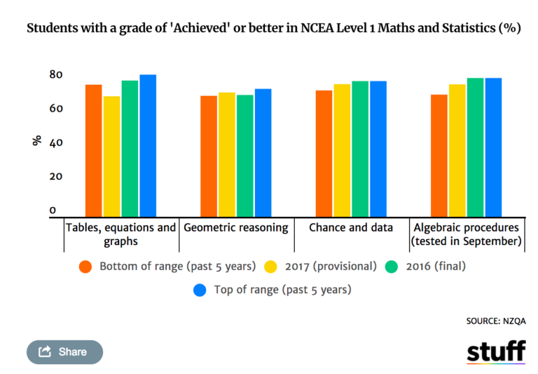
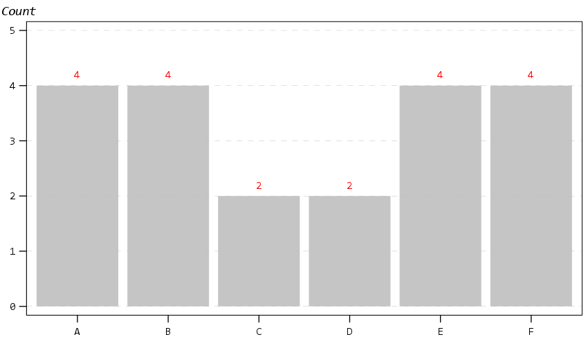
Now to start out, I show off my new color palette using a bar chart. I use a color palette derived from a Van Gogh’s bedroom as my default set. An idea I got from Sidonie Christophe (and I used this palette generator website). I also use a monospace font, Consolas, for all of the text (SPSS pulls from the system fonts, and I am a windows guy). The default font sizes are too small IMO, especially for presentations, so the X/Y axes tick labels are 14pt.

*Bar graph to show colors, title, legend.
GGRAPH
  /GRAPHDATASET NAME="graphdataset" VARIABLES=Group MEAN(X)[name="MEAN"]
  /GRAPHSPEC SOURCE=INLINE.
BEGIN GPL
  SOURCE: s=userSource(id("graphdataset"))
  DATA: Group=col(source(s), name("Group"), unit.category())
  DATA: X=col(source(s), name("MEAN"))
  GUIDE: axis(dim(1), label("Group"))
  GUIDE: axis(dim(2), label("Mean X"))
  GUIDE: legend(aesthetic(aesthetic.color.interior), label("Group"))
  GUIDE: text.title(label("Main Title"))
  GUIDE: text.subtitle(label("Subtitle"))
  SCALE: cat(dim(1), include("1", "2", "3", "4", "5", "6"))
  SCALE: linear(dim(2), include(0))
  ELEMENT: interval(position(Group*X), shape.interior(shape.square), color.interior(Group))
END GPL.

The legend I would actually prefer to have an outline box, but it doesn’t behave so nicely when I use a continuous aesthetic and pads too much. I will end the blog post with things I wish I could do with templates and/or GPL. (I wished for documentation to help me with the template for legends for example, but wish I could specify the location of the legend in inline GPL code.)

The next chart shows a scatterplot. One thing I make sure in the template is to not prevent you specifying what you want in inline GPL that is possible. So for example you could specify a default scatterplot of size 12 and the inside is grey, but as far as I can tell that prevents you from changing the color later on. Also I show a trick with using the subtitle to make a Y axis label at the top of the chart, a trick I saw originally from Naomi Robbins. (She actually prefers the text orientation on the side running north/south if you do that approach, but I prevented that in this template, I really dislike having to turn my head to read it!)

* Scatterplot, showing Y axis trick with subtitle.
* Would prefer the setStyle subtype="simple" type="scatter" works as default.
GGRAPH
  /GRAPHDATASET NAME="graphdataset" VARIABLES=X Y
  /GRAPHSPEC SOURCE=INLINE
  /FITLINE TOTAL=NO.
BEGIN GPL
  SOURCE: s=userSource(id("graphdataset"))
  DATA: X=col(source(s), name("X"))
  DATA: Y=col(source(s), name("Y"))
  GUIDE: axis(dim(1), label("X Label"))
  GUIDE: axis(dim(2))
  GUIDE: text.subtitle(label("  Y Label"))
  ELEMENT: point(position(X*Y), size(size."12"), color.interior(color."bebebe"))
END GPL.

The next chart shows off my default data labels. I have the labels positioned at the center point, and also inherit the color from the data element. So one trick I like to use is to use the polygon element to explicitly set the locations of labels (and you can draw the polygons transparent, so you only see the labels in the end). So if you want to put labels at the top of bars (or above a line graph) like Excel does, you can just shift them up a smidge.

*Label trick for bar graphs.
GGRAPH 
  /GRAPHDATASET NAME="graphdataset" VARIABLES=Group COUNT()[name="COUNT"]
  /GRAPHSPEC SOURCE=INLINE. 
BEGIN GPL 
  SOURCE: s=userSource(id("graphdataset")) 
  DATA: Group=col(source(s), name("Group"), unit.category()) 
  DATA: COUNT=col(source(s), name("COUNT")) 
  TRANS: ext = eval(COUNT + 0.2)
  GUIDE: axis(dim(1)) 
  GUIDE: axis(dim(2)) 
  GUIDE: text.subtitle(label("Count")) 
  SCALE: cat(dim(1), include("1", "2", "3", "4", "5", "6")) 
  SCALE: linear(dim(2), include(0)) 
  ELEMENT: interval(position(Group*COUNT), color.interior(color."bebebe")) 
  ELEMENT: polygon(position(Group*ext), label(COUNT), color.interior(color.red),
                    transparency.interior(transparency."1"), transparency.exterior(transparency."1")) 
END GPL.

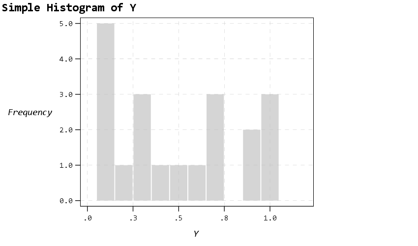
Next up is a histogram. SPSS has an annoying habit of publishing a statistics summary frame with mean/standard deviation when you make a histogram. Unfortunately the only solution I have found to this is to still generate the frame, but it is invisible so doesn’t show anything. It still takes up space in the chart area though, so the histogram will be shrunk to be somewhat smaller in width. Also I was unable to find a solution to not print the Frequency numbers with decimals here. (You can use setTickLabelFormat to say no decimals, but then that applies to all charts by default. SPSS typically chooses the numeric format from the data, but here since it calculates it inline GPL, there is no way to specify it in advance that I know of.)

* Histogram, no summary frame.
* Still not happy with Frequency numbers, stat summary is there but is empty.
GGRAPH
  /GRAPHDATASET NAME="graphdataset" VARIABLES=Y
  /GRAPHSPEC SOURCE=INLINE.
BEGIN GPL
  SOURCE: s=userSource(id("graphdataset"))
  DATA: Y=col(source(s), name("Y"))
  GUIDE: axis(dim(1), label("Y"))
  GUIDE: axis(dim(2), label("Frequency"))
  GUIDE: text.title(label("Simple Histogram of Y"))
  ELEMENT: interval(position(summary.count(bin.rect(Y, binWidth(0.1), binStart(-0.05) ))),
                    color.interior(color."bebebe"), color.exterior(color.white), 
                    transparency.interior(transparency."0.35"), transparency.exterior(transparency."0.35"))
END GPL.

The next few charts I will illustrate how SPSS pulls the axes label formats from the data itself. So first I create a few new variables for percentages, dollars, and long values with comma groupings. Additionally a new part of this template is I was able to figure out how to set the text style for small multiple panels (they are ticked like tick marks for X/Y axes). So this illustrates my favorite way to mark panels.

* Small multiple columns, illustrating different variable formats.
COMPUTE XPct = X*100.
COMPUTE YDollar = Y * 5000.
COMPUTE YComma = Y * 50000.
*Can also do PCT3.1, DOLLAR5.2, COMMA 4.1, etc.
FORMATS XPct (PCT3) YDollar (DOLLAR4) YComma (COMMA7).
EXECUTE. 

GGRAPH
  /GRAPHDATASET NAME="graphdataset" VARIABLES=XPct YDollar Pair
  /GRAPHSPEC SOURCE=INLINE
  /FITLINE TOTAL=NO.
BEGIN GPL
  SOURCE: s=userSource(id("graphdataset"))
  DATA: X=col(source(s), name("XPct"))
  DATA: Y=col(source(s), name("YDollar"))
  DATA: Pair=col(source(s), name("Pair"), unit.category())
  GUIDE: axis(dim(1), label("X Label"))
  GUIDE: axis(dim(2), label("Y Label"))
  GUIDE: axis(dim(3), opposite())
  ELEMENT: point(position(X*Y*Pair), size(size."12"), color.interior(color."bebebe"))
END GPL.

That is to make panels in columns, but you can also do it in rows. And again I prevent all the text I can from turning vertical up/down, and force it to write the text horizontally.

* Small multiple rows.
GGRAPH
  /GRAPHDATASET NAME="graphdataset" VARIABLES=X YComma Pair
  /GRAPHSPEC SOURCE=INLINE
  /FITLINE TOTAL=NO.
BEGIN GPL
  SOURCE: s=userSource(id("graphdataset"))
  DATA: X=col(source(s), name("X"))
  DATA: Y=col(source(s), name("YComma"))
  DATA: Pair=col(source(s), name("Pair"), unit.category())
  GUIDE: axis(dim(1), label("X Label"))
  GUIDE: axis(dim(2), label("Y Label"))
  GUIDE: axis(dim(4), opposite())
  ELEMENT: point(position(X*Y*1*Pair))
END GPL.

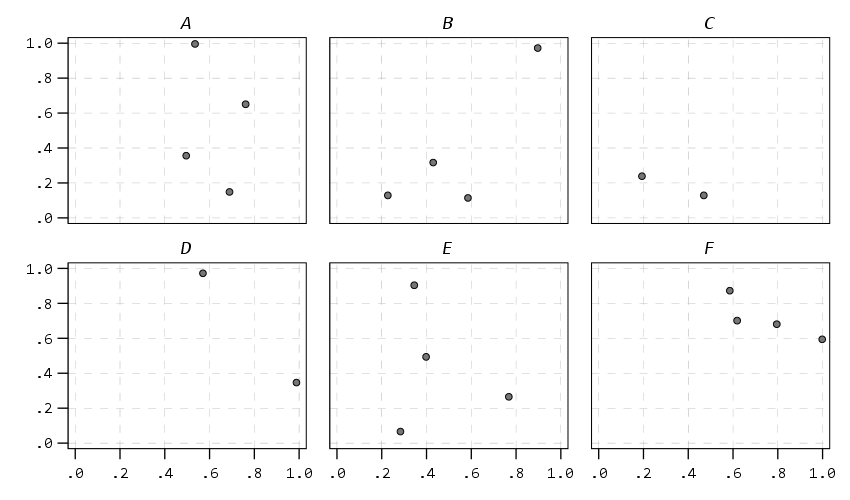
And finally if you do wrapped panels and set the facet label to opposite, it puts the grid label on the top of the panel.

* Small multiple wrap.
GGRAPH
  /GRAPHDATASET NAME="graphdataset" VARIABLES=X Y Group
  /GRAPHSPEC SOURCE=INLINE
  /FITLINE TOTAL=NO.
BEGIN GPL
  SOURCE: s=userSource(id("graphdataset"))
  DATA: X=col(source(s), name("X"))
  DATA: Y=col(source(s), name("Y"))
  DATA: Group=col(source(s), name("Group"), unit.category())
  COORD: rect(dim(1,2), wrap())
  GUIDE: axis(dim(1))
  GUIDE: axis(dim(2))
  GUIDE: axis(dim(3), opposite())
  ELEMENT: point(position(X*Y*Group))
END GPL.

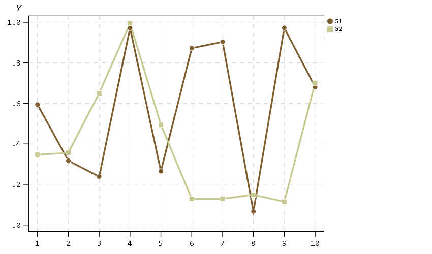
Next up I show how my default colors do with line charts, I typically tell people to avoid yellow for lines, but this tan color does alright I think. (And Van Gogh was probably color blind, so it works out well for that.) I have not tested out printing in grey-scale, I don’t think it will work out well for that beyond just the first two colors.

* Multiple line chart (long format).
GGRAPH
  /GRAPHDATASET NAME="graphdataset" VARIABLES=Time Y TGroup
  /GRAPHSPEC SOURCE=INLINE.
BEGIN GPL
  SOURCE: s=userSource(id("graphdataset"))
  DATA: Time=col(source(s), name("Time"))
  DATA: Y=col(source(s), name("Y"))
  DATA: TGroup=col(source(s), name("TGroup"), unit.category())
  SCALE: linear(dim(1), min(1))
  GUIDE: axis(dim(1), delta(1))
  GUIDE: axis(dim(2))
  GUIDE: legend(aesthetic(aesthetic.color.interior))
  GUIDE: legend(aesthetic(aesthetic.size), label("Size Y"))
  GUIDE: text.subtitle(label("   Y"))
  SCALE: cat(aesthetic(aesthetic.color.interior), include("0", "1"))
  ELEMENT: line(position(Time*Y), color.interior(TGroup))
  ELEMENT: point(position(Time*Y), shape(TGroup), color.interior(TGroup),
                    color.exterior(color.white), size(size."10")) )
END GPL.

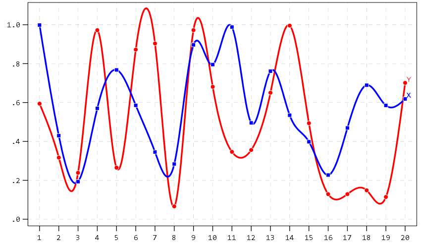
A nice approach that forgoes the legend though with line charts is to label the ends of the lines, and I show that below. Also the data above is in long format, and when superimposing points does not quite work out perfectly (G2 should always be above G1, but sometimes the G1 point is above the G2 line). Drawing each individual line in wide format though you can prevent that from happening (but results in more work to write the GPL, need several ELEMENT statements for a single line). I also show how to use splines here, which can sometimes help disentangle the spaghetti lines, but user beware, the interpolated spline values can be misleading (one of the reasons I like superimposing the point markers as well).

* Multiple line chart with end labels (wide format).
AGGREGATE OUTFILE=* MODE=ADDVARIABLES OVERWRITE=YES
  /BREAK
  /LastTime = MAX(Id).
IF Id = LastTime IdLabel = Id.
FORMATS IdLabel (F2.0).
EXECUTE.

GGRAPH
  /GRAPHDATASET NAME="graphdataset" VARIABLES=Id X Y IdLabel
   MISSING=VARIABLEWISE
  /GRAPHSPEC SOURCE=INLINE.
BEGIN GPL
  SOURCE: s=userSource(id("graphdataset"))
  DATA: Id=col(source(s), name("Id"))
  DATA: IdLabel=col(source(s), name("IdLabel")) 
  DATA: X=col(source(s), name("X"))
  DATA: Y=col(source(s), name("Y"))
  DATA: TGroup=col(source(s), name("TGroup"), unit.category())
  SCALE: linear(dim(1), min(1))
  SCALE: linear(dim(2), max(1.08))
  GUIDE: axis(dim(1), delta(1))
  GUIDE: axis(dim(2))
  SCALE: cat(aesthetic(aesthetic.color.interior), include("0", "1"))
  ELEMENT: line(position(smooth.spline(Id*Y)), color(color.red))
  ELEMENT: line(position(smooth.spline(Id*X)), color(color.blue))
  ELEMENT: point(position(Id*Y), color.interior(color.red), color.exterior(color.white),
                    size(size."9"), shape(shape.circle))
  ELEMENT: point(position(Id*X), color.interior(color.blue), color.exterior(color.white),
                    size(size."8"), shape(shape.square))
  ELEMENT: point(position(IdLabel*Y), color(color.red), label("Y"), 
                    transparency.interior(transparency."1"), transparency.exterior(transparency."1"))
  ELEMENT: point(position(IdLabel*X), color(color.blue), label("X"), 
                    transparency.interior(transparency."1"), transparency.exterior(transparency."1"))
END GPL.

A final example I illustrate is an error bar chart, but also include a few different notes about line breaks. You can use a special \n character in labels to break lines where you want. Also had a request for labeling the ends of the chart as well. Here I fudge that look by adding in a bunch of white space. This takes trial-and-error to figure out the right number of spaces to include, and can change if the Y axes labels change length, but is the least worst way I can think to do such a task. For error bars and bar graphs, it is also often easier to generate them going vertical, and just use COORD: transpose() to make them horizontal if you want.

* Error Bar chart.
VALUE LABELS Pair
  0 'Group\nOne'
  1 'Group\nTwo'
.
GGRAPH
  /GRAPHDATASET NAME="graphdataset" VARIABLES=Pair MEANCI(Y, 95)[name="MEAN_Y" LOW="MEAN_Y_LOW" 
    HIGH="MEAN_Y_HIGH"] MISSING=LISTWISE REPORTMISSING=NO
  /GRAPHSPEC SOURCE=INLINE.
BEGIN GPL
  SOURCE: s=userSource(id("graphdataset"))
  DATA: Pair=col(source(s), name("Pair"), unit.category())
  DATA: MEAN_Y=col(source(s), name("MEAN_Y"))
  DATA: LOW=col(source(s), name("MEAN_Y_LOW"))
  DATA: HIGH=col(source(s), name("MEAN_Y_HIGH"))
  COORD: transpose()
  GUIDE: axis(dim(1))
  GUIDE: axis(dim(2), label("Low Anchor                                                    High Anchor", "\nLine 2"))
  GUIDE: text.title(label("Simple Error Bar Mean of Y by Pair\n[Transposed]"))
  GUIDE: text.footnote(label("Error Bars: 95% CI"))
  SCALE: cat(dim(1), include("0", "1"), reverse() )
  SCALE: linear(dim(2), include(0))
  ELEMENT: interval(position(region.spread.range(Pair*(LOW+HIGH))), shape.interior(shape.ibeam))
  ELEMENT: point(position(Pair*MEAN_Y), size(size."12"))
END GPL.

Going to back to some scatterplots, I will illustrate a continuous legend example using size of points in a scatterplot. For size elements it typically makes sense to use a square root scale instead of a linear one (SPSS default power scale is to x^0.5, so a square root). If you go to edit the chart and click on the legend, you will see here what I mean by the excessive padding of white space at the bottom. (Also wish you could control the breaks that are shown in inline GPL, breaks for non-linear scales though are no doubt tricky.)

* Continuous legend example.
GGRAPH
  /GRAPHDATASET NAME="graphdataset" VARIABLES=X Y
  /GRAPHSPEC SOURCE=INLINE
  /FITLINE TOTAL=NO.
BEGIN GPL
  SOURCE: s=userSource(id("graphdataset"))
  DATA: X=col(source(s), name("X"))
  DATA: Y=col(source(s), name("Y"))
  GUIDE: axis(dim(1), label("X Label"))
  GUIDE: axis(dim(2))
  GUIDE: text.subtitle(label("  Y Label"))
  GUIDE: legend(aesthetic(aesthetic.size), label("SizeLab"))
  SCALE: linear(dim(2), max(1.05))
  SCALE: pow(aesthetic(aesthetic.size), aestheticMinimum(size."6px"), 
               aestheticMaximum(size."30px"), min(0), max(1))
  ELEMENT: point(position(X*Y), size(Y), color.interior(color."bebebe"))
END GPL.

And you can also do multiple legends as well. SPSS does a good job blending them together in this example, but to label the group you need to figure out which hierarchy wins first I guess.

* Multiple legend example.
GGRAPH
  /GRAPHDATASET NAME="graphdataset" VARIABLES=X Y Pair
  /GRAPHSPEC SOURCE=INLINE
  /FITLINE TOTAL=NO.
BEGIN GPL
  SOURCE: s=userSource(id("graphdataset"))
  DATA: X=col(source(s), name("X"))
  DATA: Y=col(source(s), name("Y"))
  DATA: Pair=col(source(s), name("Pair"), unit.category())
  GUIDE: axis(dim(1), label("X Label"))
  GUIDE: axis(dim(2))
  GUIDE: text.subtitle(label("  Y Label"))
  GUIDE: legend(aesthetic(aesthetic.color.interior), label("Color/Shape Lab"))
  GUIDE: legend(aesthetic(aesthetic.size), label("Size & Trans. Lab"))
  SCALE: linear(dim(2), max(1.05))
  SCALE: linear(aesthetic(aesthetic.size), aestheticMinimum(size."6px"), 
               aestheticMaximum(size."30px"), min(0), max(1))
  SCALE: linear(aesthetic(aesthetic.transparency.interior), aestheticMinimum(transparency."0"), 
               aestheticMaximum(transparency."0.6"), min(0), max(1))
  ELEMENT: point(position(X*Y), transparency.interior(Y), 
                            shape(Pair), size(Y), color.interior(Pair))
END GPL.

But that is not too shabby for just out of the box and no post-hoc editing.

Wishes for GPL and Templates

So I have put in my comments on things I wish I could do via chart templates. For a recap some documentation on what is possible, turning off the summary statistics for histograms entirely (not just making it invisible), padding for continuous legends, and making the setStyle defaults for the various charts styleOnly are a few examples. And then there are some parts I wish you could do in inline GPL, such as setting the location of the legend. Also I would not mind having access to any of these elements in inline GPL as well, such as say setting the number format in a GUIDE statement I think would make sense. (I have no idea how hard/easy these things though are under the hood.) But no documentation for templates is a real hassle when trying to edit your own.

Do y’all have any other suggestions for a chart template? Other default charts I should check out to see how my template does? Other suggested color scales? Let me know your thoughts!

Graphing Spline Predictions in SPSS

I might have around 10 blog posts about using splines in regression models – and you are about to get another. Instead of modeling non-linear effects via polynomial terms (e.g. including x^2, x^3 in a model, etc.), splines are a much better default procedure IMO. For a more detailed mathy exposition on splines and a walkthrough of the functions, see my class notes.

So I had a few questions about applying splines in generalized linear models and including control variables in my prior post (on a macro to estimate the spline terms). These include can you use them in different types of generalized linear models (yes), can you include other covariates into the model (yes). For either of those cases, interpreting the splines are more difficult though. I am going to show an example here of how to do that.

Additionally I have had some recent critiques of my paper on CCTV decay effects. One is that the locations of the knots we chose in that paper is arbitrary. So while that is true, one of the reasons I really like splines is that they are pretty robust – you can mis-specify the knot locations, and if you have enough of them they will tend to fit quite a few non-linear functions. (Also a note on posting pre-prints, despite being rejected twice and under review for around 1.5 years, it has over 2k downloads and a handful of citations. The preprint has more downloads than my typical published papers do.)

So here I am going to illustrate these points using some simulated data according to a particular logistic regression equation. So I know the true effect, and will show how mis-located spline knots still recovers the true effect quite closely. This example is in SPSS, and uses my macro on estimating spline basis.

Generating Simulated Data

So first in SPSS, I define the location where I am going to save my files. Then I import my Spline macro.

* Example of splines for generalized linear models 
* and multiple variables.

DATASET CLOSE ALL.
OUTPUT CLOSE ALL.

* Spline Macro.
FILE HANDLE macroLoc /name = "C:\Users\andre\OneDrive\Desktop\Spline_SPSS_Example".
INSERT FILE = "macroLoc\MACRO_RCS.sps".

Second, I create a set of synthetic data, in which I have a linear changepoint effect at x = 0.42. Then I generate observations according to a particular logistic regression model, with not only the non-linear X effects, but also two covariates Z1 (a binary variable) and Z2 (a continuous variable).

*****************************************************.
* Synthetic data.
SET SEED = 10.
INPUT PROGRAM.
LOOP Id = 1 to 10000.
END CASE.
END LOOP.
END file.
END INPUT PROGRAM.
DATASET NAME Sim.

COMPUTE X = RV.UNIFORM(0,1).
COMPUTE #Change = 0.42.
DO IF X <= #Change.
  COMPUTE XDif = 0.
ELSE.
  COMPUTE XDif = X - #Change.
END IF.
COMPUTE Z1 = RV.BERNOULLI(0.5).
COMPUTE Z2 = RV.NORMAL(0,1).  

DEFINE !INVLOGIT (!POSITIONAL  !ENCLOSE("(",")") ) 
1/(1 + EXP(-!1))
!ENDDEFINE.

*This is a linear changepoint at 0.42, other variables are additive.
COMPUTE ylogit = 1.1 + -4.3*x + 2.4*xdif + -0.4*Z1 + 0.2*Z2.
COMPUTE yprob = !INVLOGIT(ylogit).
COMPUTE Y = RV.BERNOULLI(yprob).
*These are variables you won't have in practice.
ADD FILES FILE =* /DROP ylogit yprob XDif.
FORMATS Id (F9.0) Y Z1 (F1.0) X Z2 (F3.2).
EXECUTE.
*****************************************************.

Creating Spline Basis and Estimating a Model

Now like I said, the correct knot location is at x = 0.42. Here I generate a set of regular knots over the x input (which varies from 0 to 1), at not the exact true value for the knot.

!rcs x = X loc = [0.1 0.3 0.5 0.7 0.9].

Now if you look at your dataset, there are 3 new splinex? variables. (For restricted cubic splines, you get # of knots - 2 new variables, so with 5 knots you get 3 new variables here.)

We are then going to use those new variables in a logistic regression model. We are also going to save our model results to an xml file. This allows us to use that model to score a different dataset for predictions.

GENLIN Y (REFERENCE=0) WITH X splinex1 splinex2 splinex3 Z1 Z2 
  /MODEL X splinex1 splinex2 splinex3 Z1 Z2 
      INTERCEPT=YES DISTRIBUTION=BINOMIAL LINK=LOGIT
  /OUTFILE MODEL='macroLoc\LogitModel.xml'. 

And if we look at the coefficients, you will see that the coefficients look offhand very close to the true coefficients, minus splinex2 and splinex3. But we will show in a second that those effects should be of no real concern.

Generating New Data and Plotting Predictions

So you should do this in general with generalized linear models and/or non-linear effects, but to interpret spline effects you can’t really look at the coefficients and know what those mean. You need to make plots to understand what the non-linear effect looks like.

So here in SPSS, I create a new dataset, that has a set of regularly sampled locations along X, and then set the covariates Z1=1 and Z2=0. These set values you may choose to be at some average, such as mean, median, or mode depending on the type of covariate. So here since Z1 can only take on values of 0 and 1, it probably doesn’t make sense to choose 0.5 as the set value. Then I recreate my spline basis functions using the exact sample macro call I did earlier.

INPUT PROGRAM.
LOOP #xloc = 0 TO 300.
  COMPUTE X = #xloc/300.
  END CASE.
END LOOP.
END FILE.
END INPUT PROGRAM.
DATASET NAME Fixed.
COMPUTE Z1 = 1.
COMPUTE Z2 = 0.
EXECUTE.
DATASET ACTIVATE Fixed.

*Redoing spline variables.
!rcs x = X loc = [0.1 0.3 0.5 0.7 0.9].

Now in SPSS, we score this dataset using our prior model xml file we saved. Here this generates the predicted probability from our logistic model.

MODEL HANDLE NAME=LogitModel FILE='macroLoc\LogitModel.xml'. 
COMPUTE PredPr = APPLYMODEL(LogitModel, 'PROBABILITY', 1).
EXECUTE.
MODEL CLOSE NAME=LogitModel.

And to illustrate how close our model is, I generate what the true predicted probability should be based on our simulated data.

*Lets also do a line for the true effect to show how well it fits.
COMPUTE #change = 0.42.
DO IF X <= #change.
  COMPUTE xdif = 0.
ELSE.
  COMPUTE xdif = (X - #change).
END IF.
EXECUTE.
COMPUTE ylogit = 1.1 + -4.3*x + 2.4*xdif + -0.4*Z1 + 0.2*Z2.
COMPUTE TruePr = !INVLOGIT(ylogit).
FORMATS TruePr PredPr X (F2.1).
EXECUTE.

And now we can put these all into one graph.

DATASET ACTIVATE Fixed.
GGRAPH
  /GRAPHDATASET NAME="graphdataset" VARIABLES=X PredPr TruePr
  /FRAME INNER=YES
  /GRAPHSPEC SOURCE=INLINE.
BEGIN GPL
  SOURCE: s=userSource(id("graphdataset"))
  DATA: X=col(source(s), name("X"))
  DATA: PredPr=col(source(s), name("PredPr"))
  DATA: TruePr=col(source(s), name("TruePr"))
  GUIDE: axis(dim(1), label("X"))
  GUIDE: axis(dim(2), label("Prob"))
  SCALE: cat(aesthetic(aesthetic.shape), map(("PredPr",shape.solid),("TruePr",shape.dash)))
  ELEMENT: line(position(X*PredPr), shape("PredPr"))
  ELEMENT: line(position(X*TruePr), shape("TruePr")) 
END GPL.

So you can see that even though I did not choose the correct knot location, my predictions are nearly spot on with what the true probability should be.

Generating Predictions Over Varying Inputs

So in practice you can do more complicated models with these splines, such as allowing them to vary over different categories (e.g. interactions with other covariates). Or you may simply want to generate predicted plots such as above, but have a varying set of inputs. Here is an example of doing that; for Z1 we only have two options, but for Z2, since it is a continuous covariate we sample it at values of -2, -1, 0, 1, 2, and generate lines for each of those predictions.

*****************************************************.
* Can do the same thing, but vary Z1/Z2.

DATASET ACTIVATE Sim.
DATASET CLOSE Fixed.

INPUT PROGRAM.
LOOP #xloc = 0 TO 300.
  LOOP #z1 = 0 TO 1.
    LOOP #z2 = -2 TO 2.
      COMPUTE X = #xloc/300.
      COMPUTE Z1 = #z1.
      COMPUTE Z2 = #z2.
      END CASE.
    END LOOP.
  END LOOP.
END LOOP.
END FILE.
END INPUT PROGRAM.
DATASET NAME Fixed.
EXECUTE.
DATASET ACTIVATE Fixed.

*Redoing spline variables.
!rcs x = X loc = [0.1 0.3 0.5 0.7 0.9].

MODEL HANDLE NAME=LogitModel FILE='macroLoc\LogitModel.xml'. 
COMPUTE PredPr = APPLYMODEL(LogitModel, 'PROBABILITY', 1).
EXECUTE.
MODEL CLOSE NAME=LogitModel.

FORMATS Z1 Z2 (F2.0) PredPr X (F2.1).
VALUE LABELS Z1
  0 'Z1 = 0'
  1 'Z1 = 1'.
EXECUTE.

*Now creating a graph of the predicted probabilities over various combos.
*Of input variables.
DATASET ACTIVATE Fixed.
GGRAPH
  /GRAPHDATASET NAME="graphdataset" VARIABLES=X PredPr Z1 Z2
  /FRAME INNER=YES
  /GRAPHSPEC SOURCE=INLINE.
BEGIN GPL
  SOURCE: s=userSource(id("graphdataset"))
  DATA: X=col(source(s), name("X"))
  DATA: PredPr=col(source(s), name("PredPr"))
  DATA: TruePr=col(source(s), name("TruePr"))
  DATA: Z1=col(source(s), name("Z1"), unit.category())
  DATA: Z2=col(source(s), name("Z2"), unit.category())
  COORD: rect(dim(1,2), wrap())
  GUIDE: axis(dim(1), label("X"))
  GUIDE: axis(dim(2), label("Predicted Probability"))
  GUIDE: axis(dim(3), opposite())
  GUIDE: legend(aesthetic(aesthetic.color), label("Z2"))
  SCALE: cat(aesthetic(aesthetic.color), map(("-2",color."8c510a"),("-1",color."d8b365"),
               ("0",color."f6e8c3"), ("1",color."80cdc1"), ("2",color."018571")))
  ELEMENT: line(position(X*PredPr*Z1), color(Z2))
END GPL.
*****************************************************.

So between all of these covariates, the form of the line does not change much (as intended, I simulated the data according to an additive model).

If you are interested in drawing more lines for Z2, you may want to use a continuous color scale instead of a categorical one (see here for a similar example).

Making caterpillar plots for random effects in SPSS

For one of my classes for PhD students (in seminar research and analysis), I talk about the distinction between random effect models and fixed effect models for a week.

One of my favorite plots to go with random effect models is called a caterpillar plot. So typically folks just stop at reporting the variance of the random intercepts and slopes when they estimate these models. But you not only get the global variance estimates, but can also get an estimate (and standard error) for each higher level variable. So if I have 100 people, and I do a random intercept for those 100 people, I can say “Joe B’s random intercept is 0.5, and Jane Doe’s random intercept is -0.2” etc.

So this is halfway in between confirmatory data analysis (we used a model to get those estimates) but is often useful for further understanding the model and seeing if you should add anything else. E.g. if you see the random intercepts have a high correlation with some other piece of person information, that information should be incorporated into the model. It is also useful to spot outliers. And if you have spatial data mapping the random intercepts should be something you do.

SPSS recently made it easier to make these types of plot (as of V25), so I am going to give an example. In my class, I give code examples in R, Stata, and SPSS whenever I can, so this link contains code for all three programs. I will be using data from my dissertation, with crime on street segments in DC, nested within regular grid cells (used to approximate neighborhoods).

SPSS Code

So first data prep, I define where my data is using FILE HANDLE, read in the csv file of the data, compute a new variable (the sum of both detritus and physical infrastructure 311 calls). Then finally I declare that the FishID variable (my grid cells neighborhoods) is a nominal level variable. SPSS needs that defined correctly for later models.

*************************************************************.
FILE HANDLE data /NAME = "??????Your Path Here!!!!!!!!!!!".

*Importing the CSV file into SPSS.
GET DATA  /TYPE=TXT
  /FILE="data\DC_Crime_withAreas.csv"
  /ENCODING='UTF8'
  /DELCASE=LINE
  /DELIMITERS=","
  /QUALIFIER='"'
  /ARRANGEMENT=DELIMITED
  /FIRSTCASE=2
  /DATATYPEMIN PERCENTAGE=95.0
  /VARIABLES=
  MarID AUTO
  XMeters AUTO
  YMeters AUTO
  FishID AUTO
  XMetFish AUTO
  YMetFish AUTO
  TotalArea AUTO
  WaterArea AUTO
  AreaMinWat AUTO
  TotalLic AUTO
  TotalCrime AUTO
  CFS1 AUTO
  CFS2 AUTO
  CFS1Neigh AUTO
  CFS2Neigh AUTO
  /MAP.
CACHE.
EXECUTE.
DATASET NAME CrimeDC.
DATASET ACTIVATE CrimeDC.

*Compute a new variable, total number of 311 calls for service.
COMPUTE CFS = CFS1 + CFS2.
EXECUTE.

VARIABLE LEVEL FishID (NOMINAL).
*************************************************************.

Now onto the good stuff, estimating our model. Here we are looking at the fixed effects of bars and 311 calls on crime on street segments, but also estimating a random intercept for each grid cell. As of V25, SPSS lets you specify an option to print the solution for the random statements, which we can capture in a new SPSS dataset using the OMS command.

So first we declare our new dataset to dump the results in, Catter. Then we specify an OMS command to capture the random effect estimates, and then estimate our negative binomial model. I swear SPSS did not use to be like this, but now you need to end the OMS command before you putz with that dataset.

*************************************************************.
DATASET DECLARE Catter.

OMS
  /SELECT TABLES
  /IF SUBTYPES='Empirical Best Linear Unbiased Predictions'
  /DESTINATION FORMAT=SAV OUTFILE='Catter' VIEWER=YES
  /TAG='RandTable'.

*SOLUTION option only as of V25.
GENLINMIXED
  /FIELDS TARGET=TotalCrime
  /TARGET_OPTIONS DISTRIBUTION=NEGATIVE_BINOMIAL
  /FIXED EFFECTS=TotalLic CFS
  /RANDOM USE_INTERCEPT=TRUE SUBJECTS=FishID SOLUTION=TRUE
  /SAVE PREDICTED_VALUES(PredRanEff).

OMSEND TAG='RandTable'.
EXECUTE.
DATASET ACTIVATE Catter.
*************************************************************.

And now we can navigate over to the saved table and make our caterpillar plot. Because we have over 500 areas, I sort the results and don’t display the X axis. But this lets you see the overall distribution and spot any outliers.

*************************************************************.
*Lets make a caterpillar plot.
FORMATS Prediction Std.Error LowerBound UpperBound (F4.2).
SORT CASES BY Prediction (D).

GGRAPH
  /GRAPHDATASET NAME="graphdataset" VARIABLES=Var1 Prediction LowerBound UpperBound
  /GRAPHSPEC SOURCE=INLINE
  /FRAME INNER=YES.
BEGIN GPL
  SOURCE: s=userSource(id("graphdataset"))
  DATA: Var1=col(source(s), name("Var1"), unit.category())
  DATA: Prediction=col(source(s), name("Prediction"))
  DATA: LowerBound=col(source(s), name("LowerBound"))
  DATA: UpperBound=col(source(s), name("UpperBound"))
  SCALE: cat(dim(1), sort.data())
  GUIDE: axis(dim(1), null())
  GUIDE: axis(dim(2), label("BLUP"))
  SCALE: linear(dim(2), include(0))
  ELEMENT: edge(position(region.spread.range(Var1*(LowerBound + UpperBound))), size(size."0.5")))
  ELEMENT: point(position(Var1*Prediction), color.interior(color.black), size(size."1"))
END GPL.
*************************************************************.

And here is my resulting plot.

And I show in the linked code some examples for not only random intercepts, but you can do the same thing for random slopes. Here is an example doing a model where I let the TotalLic effect (the number of alcohol licenses on the street segment) vary by neighborhood grid cell. (The flat 0 estimates and consistent standard errors are grid cells with 0 licenses in the entire area.)

The way to interpret these estimates are as follows. The fixed effect part of the regression equation here is: 0.247 + 0.766*Licenses. That alcohol license effect though varies across the study area, some places have a random slope of +2, so the equation could then be thought of as 0.247 + (0.766 + 2)*Licenses (ignoring the random intercept part). So the effect of bars in that area is much larger. Also there are places with negative effects, so the effects of bars in those places are smaller. You can do the same type of thought experiments simply with the reported variance components, but I find the caterpillar plots to be a really good visual to show what those random effects actually mean.

For other really good multilevel modelling resources, check out the Centre for Multilevel Modelling, and Germán Rodríguez’s online notes. Eventually I will get around to uploading my seminar class notes and code snippets, but in the mean time if you see a week and would like my code examples, always feel free to email.

Sorting rates using empirical Bayes

A problem I have come across in a few different contexts is the idea of ranking rates. For example, say a police department was interested in increasing contraband recovery and are considering two different streets to conduct additional traffic enforcement on — A and B. Say street A has a current hit rate of 50/1000 for a rate of 5%, and street B has a recovery rate of 1/10 for 10%. If you just ranked by percentages, you would choose street B. But given the small sample size, targeting street B is not a great bet to actually have a 10% hit rate going forward, so it may be better to choose street A.

The idea behind this observation is called shrinkage. Your best guess for the hit rate in either location A or location B in the future is not the observed percentage, but somewhere in between the observed percentage and the overall hit rate. Say the overall hit rate for contraband recovery is only 1%, then you wouldn’t expect street B to have a 10% hit rate going forward, but maybe something closer to 2% given the very small sample size. For street A you would expect shrinkage as well, but given it is a much larger sample size you would expect the shrinkage to be much less, say a 4% hit rate going forward. In what follows I will show how to calculate that shrinking using a technique called empirical Bayesian estimation.

I wanted to apply this problem to a recent ranking of cities based on officer involved shooting rates via federalcharges.com (hat tip to Justin Nix for tweeting that article). The general idea is that you don’t want to highlight cities who have high rates simply by chance due to smaller population baselines. Howard Wainer talks about this problem of ranking resulted in the false idea that smaller schools were better based on small samples of test results. Due to the high variance small schools will be both at the top and the bottom of the distributions, even if all of the schools have the same overall mean rate. Any reasonable ranking needs to take that variance into account to avoid the same mistake.

The same idea can be applied to homicide or other crime rates. Here I provide some simple code (and a spreadsheet) so other analysts can easily replicate this sorting idea for their own problems.

Sorting OIS Shooting Rates

For this analysis I just took the reported rates by the federal changes post already aggregated to city, and added in 2010 census estimates from Wikipedia. I’d note these are not necessarily the correct denominator, some jurisdictions may cover less/more of the pop that these census designated areas. (Also you may consider other non-population denominators as well.) But just as a proof of concept I use the city population (which I suspect is what the original federal charges blog post used.)

The below graph shows the city population on the X axis, and the OIS rate per 100,000 on the Y axis. I also added in the average rate within these cities (properly taking into account that cities are different population sizes), and curves to show the 99% confidence interval funnel. You can see that the distribution is dispersed more than would be expected by the simple binomial proportions around the overall rate of close to 9 per 100,000.

The following section I have some more notes on how I calculated the shrinkage, but here is a plot that shows the original rate, and the empirical Bayes shrunk OIS rate. The arrow points to the shrunk rate, so you can see that places with smaller population proportions and those farther away from the overall rate are shrunk towards the overall OIS rate within this sample.

To see how this changes the rankings, here is a slopegraph of the before/after rankings.

So most of the rankings only change slightly using this technique. But if one incorporated cities with smaller populations though they would change even more.

The federal charges post also calculates differences in the OIS rate versus the homicide rate. That approach suffers from even worse problems in ignoring the variance of smaller population denominators (it compounds two high variance estimates), but I think the idea of adjusting for homicide rates in this context maybe has potential in a random effects binomial model (either as a covariate or a multivariate outcome). Would need to think about it/explore it some more though. Also to note is that the fatal encounters data is multiple years, so don’t be confused that OIS rates by police are larger than yearly homicide rates.

The Mathy Part, Empirical Bayes Shrinkage

There are a few different ways I have seen reported to do empirical Bayes shrinkage. One is estimating the beta distribution for the entire sample, and then creating a shrunk estimate for the observed rates for individual observations using the observed sample Beta estimates as a prior (hence empirical Bayes). David Robinson has a nice little e-book on batting averages and empirical Bayes that can be applied to basically any type of percentage estimate you are interested in.

Another way I have seen it expressed is based on the work of the Luc Anselin and the GeoDa folks using explicit formulas.

Either of these ways you can do in a spreadsheet (a more complicated way is to actually fit a random effects model), but here is a simpler run-down of the GeoDa formula for empirical shrinkage, which is what I use in the above example. (This will not necessarily be the same compared to David Robinson’s approach, see the R code in the zip file of results for comparisons to David’s batting average dataset, but are pretty similar for that example.) So you can think of the shrunk rate as a weighted average between the observed rate for location i as y_i, and the overall rate mu, where the weight is W_i.

Shrunk Rate_i = W_i*y_i + (1 - W_i)*mu

You then need to calculate the W_i weight term. Weights closer to 1 (which will happen with bigger population denominators) result in only alittle shrinkage. Weights closer to 0 (when the population denominator is small), result in much larger shrinkage. Below are the formulas and variable definitions to calculate the shrinkage.

  • i = subscript to denote area i. No subscript means it is a scalar.
  • r_i = total number of incidents (numerator) in area i
  • p_i = total population in area i (denominator)
  • y_i = observed rate in area i = r_i/p_i
  • k = total number of areas in study
  • mu = population mean rate = sum(r_i)/sum(p_i)
  • v = population variance = sum(p_i*[y_i - mu]^2]) / [sum(p_i)] - mu/(sum(p_i)/k)
  • W_i = shrinkage weight = v /[v + (mu/p_i)]

For those using R, here is a formula that takes the numerator and denominator as vectors and returns the smoothed rate based on the above formula:

#R function
shrunkrate <- function(num,den){
  sDen <- sum(den)
  obsrate <- num/den
  k <- length(num)
  mu <- sum(num)/sDen
  pav <- sDen/k
  v <- ( sum( den*(obsrate-mu)^2 ) / sDen ) - (mu/pav) 
  W <- v / (v + (mu/den))
  smoothedrate <- W*obsrate + (1 - W)*mu
  return(smoothedrate)
}

For those using SPSS I’ve uploaded macro code to do both the funnel chart lines and the shrunk rates.

For either missing values might mess things up, so eliminate them before using the functions. For those who don’t use stat software, I have also included an Excel spreadsheet that shows how to calculate the smoothed rates. It is in this zip file, along with other code and data used to replicate my graphs and results here.

For those interested in other related ideas, see

Remaking a clustered bar chart

Thomas Lumley on his blog had a recent example of remaking a clustered bar chart that I thought was a good idea. Here is a screenshot of the clustered bar chart (the original is here):

And here is Lumley’s remake:

In the original bar chart it is hard to know what is the current value (2017) and what are the past values. Also the bar chart goes to zero on the Y axis, which makes any changes seem quite small, since the values only range from 70% to 84%. Lumley’s remake clearly shows the change from 2016 to 2017, as well as the historical range from 2011 through 2016.

I like Lumley’s remake quite alot, so I made some code in SPSS syntax to show how to make a similar chart. The grammar of graphics I always thought is alittle confusing when using clustering, so this will be a good example demonstration. Instead of worrying about the legend I just added in text annotations to show what the particular elements were.

One additional remake is instead of offsetting the points and using a slope chart (this is an ok use, but see my general critique of slopegraphs here) is to use a simpler dotplot showing before and after.

One reason I do not like the slopes is that slope itself is dictated by the distance from 16 to 17 in the chart (which is arbitrary). If you squeeze them closer together the slope gets higher. The slope itself does not encode the data you want, you want to calculate the difference from beginning to end. But it is not a big difference here (my main complaints for slopegraphs are when you superimpose many different slopes that cross one another, in those cases I think a scatterplot is a better choice).

Jonathan Schwabish on his blog often has similar charts (see this one example).

Pretty much all clustered bar charts can be remade into either a dotplot or a line graph. I won’t go as far as saying you should always do this, but I think dot plots or line graphs would be a better choice than a clustered bar graph for most examples I have seen.

Here like Lumley said instead of showing the ranges likely a better chart would just be a line chart over time of the individual years, that would give a better since of both trends as well as typical year-to-year changes. But these alternatives to a clustered bar chart I do not think turned out too shabby.


SPSS Code to replicate the charts. I added in the labels for the elements manually.

**********************************************************************************************.
*data from https://www.stuff.co.nz/national/education/100638126/how-hard-was-that-ncea-level-1-maths-exam.
*Motivation from Thomas Lumley, see https://www.statschat.org.nz/2018/01/18/better-or-worse/.

DATA LIST FREE / Type (A10) Low Y2017 Y2016 High (4F3.1).
BEGIN DATA
Tables 78.1 71.2 80.5 84
Geo 71.5 73.5 72 75.6
Chance 74.7 78.4 80.2 80.2
Algebra 72.2 78.3 82 82
END DATA.
DATASET NAME Scores.
VALUE LABELS Type
  'Tables' 'Tables, equations, and graphs'
  'Geo' 'Geometric Reasoning'
  'Chance' 'Chance and data'
  'Algebra' 'Algebraic procedures'
.
FORMATS Low Y2017 Y2016 High (F3.0).
EXECUTE.

*In this format I can make a dot plot.
GGRAPH
  /GRAPHDATASET NAME="graphdataset" VARIABLES=Y2017 Y2016 Low High Type 
  /GRAPHSPEC SOURCE=INLINE.
BEGIN GPL
  SOURCE: s=userSource(id("graphdataset"))
  DATA: Y2017=col(source(s), name("Y2017"))
  DATA: Y2016=col(source(s), name("Y2016"))
  DATA: Low=col(source(s), name("Low"))
  DATA: High=col(source(s), name("High"))
  DATA: Type=col(source(s), name("Type"), unit.category())
  GUIDE: axis(dim(1), delta(1), start(70))
  GUIDE: axis(dim(1), label("Percent Students with a grade of 'Achieved' or better"), opposite(), delta(100), start(60))
  GUIDE: axis(dim(2))
  SCALE: cat(dim(2), include("Algebra", "Chance", "Geo", "Tables"))
  ELEMENT: edge(position((Low+High)*Type), size(size."30"), color.interior(color.grey), 
           transparency.interior(transparency."0.5"))
  ELEMENT: edge(position((Y2016+Y2017)*Type), shape(shape.arrow), color(color.black), size(size."2"))
  ELEMENT: point(position(Y2016*Type), color.interior(color.black), shape(shape.square), size(size."10"))
END GPL.

*Now trying a clustered bar graph.
GGRAPH
  /GRAPHDATASET NAME="graphdataset" VARIABLES=Y2017 Y2016 Low High Type 
  /GRAPHSPEC SOURCE=INLINE.
BEGIN GPL
  SOURCE: s=userSource(id("graphdataset"))
  DATA: Y2017=col(source(s), name("Y2017"))
  DATA: Y2016=col(source(s), name("Y2016"))
  DATA: Low=col(source(s), name("Low"))
  DATA: High=col(source(s), name("High"))
  DATA: Type=col(source(s), name("Type"), unit.category())
  TRANS: Y17 = eval("2017")
  TRANS: Y16 = eval("2016")
  COORD: rect(dim(1,2), cluster(3,0))
  GUIDE: axis(dim(3))
  GUIDE: axis(dim(2), label("% Achieved"), delta(1), start(70))
  ELEMENT: edge(position(Y16*(Low+High)*Type), size(size."30"), color.interior(color.grey), 
           transparency.interior(transparency."0.5"))
  ELEMENT: edge(position((Y16*Y2016*Type)+(Y17*Y2017*Type)), shape(shape.arrow), color(color.black), size(size."2"))
  ELEMENT: point(position(Y16*Y2016*Type), color.interior(color.black), shape(shape.square), size(size."10"))
END GPL.

*This can get tedious if you need to make a line for many different years.
*Reshape to make a clustered chart in a less tedious way (but cannot use arrows this way).
VARSTOCASES /MAKE Perc FROM Y2016 Y2017 /INDEX Year.
COMPUTE Year = Year + 2015.
DO IF Year = 2017.
  COMPUTE Low = $SYSMIS.
  COMPUTE High = $SYSMIS.
END IF.
EXECUTE.

GGRAPH
  /GRAPHDATASET NAME="graphdataset" VARIABLES=Type Perc Year Low High MISSING=VARIABLEWISE REPORTMISSING=NO
  /GRAPHSPEC SOURCE=INLINE.
BEGIN GPL
  SOURCE: s=userSource(id("graphdataset"))
  DATA: Type=col(source(s), name("Type"), unit.category())
  DATA: Perc=col(source(s), name("Perc"))
  DATA: Low=col(source(s), name("Low"))
  DATA: High=col(source(s), name("High"))
  DATA: Year=col(source(s), name("Year"), unit.category())
  COORD: rect(dim(1,2), cluster(3,0))
  GUIDE: axis(dim(3))
  GUIDE: axis(dim(2), label("% Achieved"), delta(1), start(70))
  SCALE: cat(dim(3), include("Algebra", "Chance", "Geo", "Tables"))
  ELEMENT: edge(position(Year*(Low+High)*Type), color.interior(color.grey), size(size."20"), transparency.interior(transparency."0.5"))
  ELEMENT: path(position(Year*Perc*Type), split(Type))  
  ELEMENT: point(position(Year*Perc*Type), size(size."8"), color.interior(color.black), color.exterior(color.white))
END GPL.
**********************************************************************************************.


Using FILE HANDLE in SPSS

To aid in reproducible analysis, I often have a set of FILE HANDLE commands at the header of my syntax. For example, here is basically what most of my syntax’s look like at the top.

DATASET CLOSE ALL.
OUTPUT CLOSE ALL.

*Simple description here of what the syntax does.

FILE HANDLE data /NAME = "H:\ProjectX\OriginalData".
FILE HANDLE save /NAME = "C:\Users\axw161530\Dropbox\Documents\BLOG\FileHandles_SPSS".

What those commands go are point to particular locations on my machine that either have the data I will use for the syntax, and where to save the subsequent results. So what this does instead of having to write something like:

GET FILE = "H:\ProjectX\OriginalData\SPSS_Dataset1.sav".

I can just write something like:

GET FILE = "data\SPSS_Dataset1.sav".

The same works for where I save the files, so I would use the second SAVE line instead of the first after I’ve defined a file handle.

*SAVE OUTFILE = "C:\Users\axw161530\Dropbox\Documents\BLOG\FileHandles_SPSS\TransformedData1.sav"
SAVE OUTFILE = "save\TransformedData1.sav"

Besides being shorter, this greatly aids when you need to move files around. Say I needed to move where I saved the files from my personal drive to a work H drive. If you use file handles, all you need to do is change the one line of code at the top of your syntax. If you used absolute references you would need to edit the file at every location you used that absolute path (e.g. every GET FILE, or GET TRANSLATE, or SAVE).

Another trick you can use is that you can stack multiple file handles together. Consider this example.

FILE HANDLE base /NAME = "H:\ProjectX".
FILE HANDLE data /NAME = "base\Datasets"
FILE HANDLE report /NAME = "base\Reports"

In this case I defined a base location, and then defined the data and report file handles as folders within the base file handle. Again if you need to move this entire project, all you need to do is edit that original base file handle location.

A final note, if I have a set of complicated code that I split up into multiple syntax files, one trick you can use is to place all of your file handles into one set of syntax, and then use INSERT to call that syntax. Depending on the structure though you may need to edit the INSERT call though at the header for all of the sub-syntaxes, so it may not be any less work.

I should also mention you could use the CD command to some of the same effect. So instead of defining a save file handle, you could do:

CD "C:\Users\axw161530\Dropbox\Documents\BLOG\FileHandles_SPSS".
SAVE OUTFILE = "TransformedData1.sav"

I don’t typically change SPSS’s current directory, but there are legitimate reasons to do so. If SPSS needs write access to the directory in particular, this is sometimes easier than dealing with permissions. That does not come up often for me, and most of the time I have data files in many different places, so I typically just stick with using file handles.

Accessing FILE HANDLES in Python or R

If you are using file handles in SPSS code, you may want to be able to access those file handles the same way in Python or R code called within SPSS. This may be for much of the same reason — you may want to access data or save data in those programs, but use the file handles you have identified. Albert-Jan Roskam on the Nabble group showed how to do this.

So for python you could do below:

BEGIN PROGRAM Python.
import spssaux

#Getting the SPSS file handles
file_handles = spssaux.FileHandles().resolve

#Grabbing a particular handle
data_loc = file_handles('data')

#Setting the python directory to the save location
import os
os.chdir(file_handles('save'))
END PROGRAM.

And for R you can do:

BEGIN PROGRAM R.
fh <- spssdata.GetFileHandles()
file_handles <- sapply(fh, function(x) x[2])
names(file_handles) <-  sapply(fh, function(x) x[1])

#Accessing a particular file handle
file_handles["data"]

#setting the R directory to save handle
setwd(file_handles["save"])
END PROGRAM.

In either case it is nice so you again can just edit one line at the top of your syntax if you change file locations, instead of having to edit multiple lines in the subsequent syntax file.